Description
Product Structure
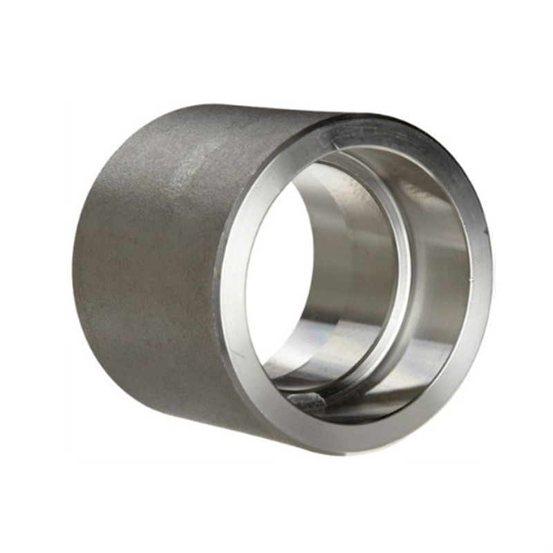
ANSI/ASME B16.11 Socket Weld Full Coupling Standard Specification Socket Weld Full Coupling Sizes| Dimensions | ASME 16.11, MSS SP-79, MSS SP-95, 83, 95, 97, BS 3799 |
| Size | 1/8″ NB TO 4″ NB |
| Pressure Ratings | 2000 LBS, 3000 LBS, 6000 LBS, 9000 LBS |
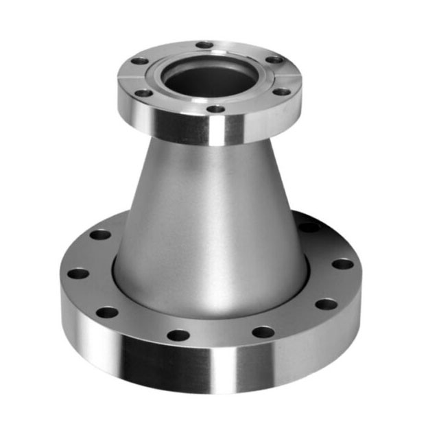
| Form | Full Couplings, Reducing Coupling |
| Production Grades | Stainless Steel, Alloy Steel, Duplex, Nickel Alloys, Low temperature Steel, Carbon Steel, Cupro Nickel |
| ASME: | ASME 16.11, MSS SP-79, MSS SP-95, 83, 95, 97, BS 3799 |
| DIN: | DIN2605, DIN2615, DIN2616, DIN2617, DIN28011 |
| EN: | EN10253-1, EN10253-2 |
| Forged Socket weld Full Coupling | Socket Weld Full Coupling Class 3000 |
| Socket Weld Reducing Coupling | 3 4 Socket Weld Full Coupling |
| ASME B16.11 Socket Weld Reducing Coupling | 3000LB Socket Weld Full Coupling |
| ANSI B16.11 Forged Socket Weld Full Coupling | Class 6000 Socket Weld Full Coupling |
| Socket Weld Full Coupling Weight | BS 3799 Forged Socket Weld Full Coupling |
| Socket Weld Full Coupling Reducers | High Quality Socket weld Full Coupling |
| 2 Socket Weld Full Coupling | 1/2 Socket Weld Full Coupling |
| 3000# Forged Socket Weld Full Coupling | 3/4 Socket Weld Full Coupling |
| 5 Socket Weld Full Coupling | 1 inch Socket Weld Full Coupling |
| 8 Socket Weld Full Coupling | 2 inch Socket Weld Full Coupling |
| 6000# Socket Weld Full Coupling | 3 inch Socket Weld Full Coupling |
| 6 Socket Weld Full Coupling | 6 inch Socket Weld Full Coupling |
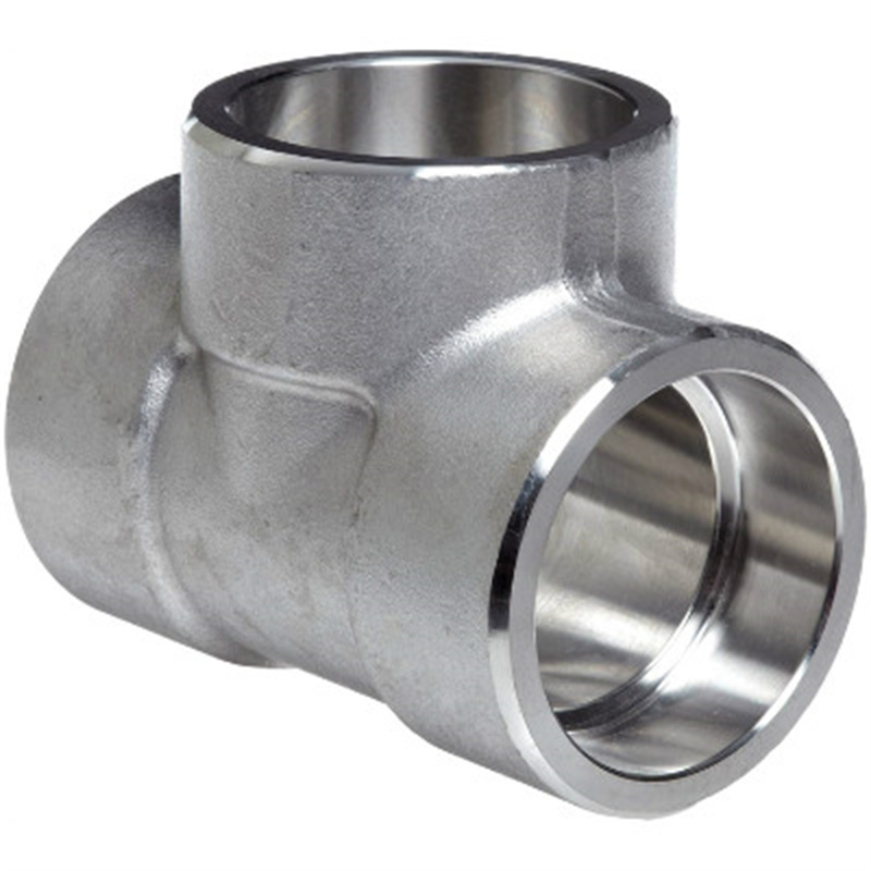
 As an ISO certified company, Liaocheng Shenghao Metal products Co., LTD has made its way into the national and international markets as one of the leading distributors, supplier and stockist of Socket Weld Full Coupling. Socket Weld Full Couplings are used to connect small bore pipes as a projection of a welding effect on the pipe bore. Both the ends of these Full Couplings are threaded. They are highly demanded in the pipe fitting market. These Stainless Steel Socket Weld Half Couplings are rigorously tested to ensure the highest quality and endurance under any extreme conditions. These ANSI B16.11 Forged Socket Weld Full Couplings are used in applications such as pharmaceuticals, shipbuilding, etc. HGFF Group Co., Ltd. owers their clientele the ASME B16.11 Forged Socket Weld Full Couplings at reasonable prices. They are provided in different sizes and thickness for the specific needs of the customers.
Technical Parameters
ANSI/ASME B16.11 SOCKET WELD FULL COUPLING DIMENSIONS Socket Weld Reducing Coupling Dimensions 3000# Socket Weld Coupling Dimensions
 | NPS | Socket Bore | Depth Socket | Bore DIA | Socket wall THK |
| B | J | D | C | |
| 1/2 | 21.95 21.70 | 10 | 16.6 15 | 4.65 4.10 |
| 3/4 | 27.30 27.05 | 13 | 21.7 20.2 | 4.90 4.25 |
| 1 | 34.05 33.80 | 13 | 27.4 25.9 | 5.70 5.00 |
| 1.1/4 | 42.80 42.55 | 13 | 35.8 34.3 | 6.05 5.30 |
| 1.1/2 | 48.90 48.65 | 13 | 41.7 40.1 | 6.35 5.55 |
| 2 | 61.35 61.10 | 16 | 53.5 51.7 | 6.95 6.05 |
| 2.1/2 | 74.20 73.80 | 16 | 64.2 61.2 | 8.75 7.65 |
| 3 | 90.15 89.80 | 16 | 79.5 46.4 | 9.50 8.30 |
| 4 | 115.80 115.45 | 19 | 103.8 100.7 | 10.70 9.35 |
| NPS | Laying lengths | |||
| Coupling E | Half coupling F | |||
| 1/2 | 9.5 | 22.5 | ||
| 3/4 | 9.5 | 23.5 | ||
| 1 | 13 | 29 | ||
| 1.1/4 | 13 | 30 | ||
| 1.1/2 | 13 | 32 | ||
| 2 | 19 | 41 | ||
| 2.1/2 | 19 | 42.5 | ||
| 3 | 19 | 44.5 | ||
| 4 | 19 | 47.5 | ||
General notes
Dimensions are in millimeters unless otherwise indicated. Socket Bore (B) – Maximum and minimum dimensions. Bore Diameter (D) – Maximum and minimum dimensions. Socket wall thickness – (C) – Average of Socket wall thickness. Dimensional tolerances center to the bottom of the socket – (A) NPS 1/2 and NPS 3/4 = +/- 1.5 mm NPS 1 to NPS 2 = +/- 2 mm NPS 2.1/2 to NPS 4 = +/- 2.5 mm
| NPS | Socket Bore | Depth Socket | Bore DIA | Socket wall THK |
| B | J | D | C | |
| 1/2 | 21.95 21.70 | 10 | 12.5 11 | 5.95 5.20 |
| 3/4 | 27.30 27.05 | 13 | 16.3 14.8 | 6.95 6.05 |
| 1 | 34.05 33.80 | 13 | 21.5 19.9 | 7.90 6.95 |
| 1.1/4 | 42.80 42.55 | 13 | 30.2 28.7 | 7.90 6.95 |
| 1.1/2 | 48.90 48.65 | 13 | 34.7 33.2 | 8.90 7.80 |
| 2 | 61.35 61.10 | 16 | 43.6 42.1 | 10.90 9.50 |
| NPS | Laying lengths | |||
| Coupling E | Half coupling F | |||
| 1/2 | 9.5 | 22.5 | ||
| 3/4 | 9.5 | 23.5 | ||
| 1 | 13 | 29 | ||
| 1.1/4 | 13 | 30 | ||
| 1.1/2 | 13 | 32 | ||
| 2 | 19 | 41 | ||


